Power fets – how they work (art111) Power smps mosfet transistor amplifier using circuit add component list Mosfet circuit amplifier power diagram audio schematics transistor car examples subwoofer choose board
switch mode power supply - How to adjust this circuit to use N-Mosfet
Circuit 12v charger battery smps diagram amp transformerless transformer schematic supply power mosfet mobile without 24v using simple 5a voltage Smps 12v 24v power 2a 3a outputs two supply using circuits electrical switch max Smps circuit diagram using mosfet
Inverter circuit diagram using sg3524 and mosfet
14+ smps circuit diagram using mosfetSmps mosfet using charger nicad nerv Circuit smps mosfet schematic values nervSmps power amplifier using 2 mosfet transistor.
Mosfet as a power supply output switchSmps circuit 12v mosfet 24v amp circuits diagram transformer homemade details component coil adapter Mosfet in smpsSwitch mode power supply.

Multiple output smps circuit
Smps circuit cheapest using simple 220v circuitsCheapest smps circuit using mje13005 Smps circuit diagram using mosfetSimple mosfet switching circuit – how to turn on / turn off n-channel.
Mosfet circuit.jpgSmps circuit diagram using mosfet 12v, 24v, 1 amp mosfet smps circuitDo it by self with wiring diagram: simple mosfet amplifier pcb circuit.

Mosfet circuit power supply smps switch mode adjust instead use two stack
Power supplySmps mosfet regulator transistor Simple 12v, 1 amp smps with pcb and transformer winding detailsSmps mosfet 90w driven 12v.
Mosfet amplifier circuit audio schematic diagram pcb simple transistor radio using choose boardMosfet high side channel power supply drive driving isolated current switch low switching when output eevblog going need if just Smps mosfet fetsSmps mosfet allaboutcircuits.

Supply power switching circuit schematic diagram output multiple smps dc switch circuits ac regulator mode bridge ic half transformer tl494
Smps circuit diagram using mosfetThe inexpensive, simple, mosfet a.m. linear project Circuit smps mosfet 12v inverter mosfetsHigh-power switching using mosfets.
Mosfet using schematic help circuitlab createdSmps circuits transformer Mosfets switching power using highMosfet power supply diagram circuit explained voltage jumpers understand struggling bottom change am.

Mosfet circuit help needed question load work
12v, 24v, 1 amp mosfet smps circuitMosfet switching mosfets circuits normally Amplifier schematic linear overall mosfetNovagraph chartist 5.0.
Inverter mosfet 555 ne555 timer eleccircuit sine sg3524 volts schematics 50hz transformer frequency amplifier figure1Smps circuit 12v amp mosfet coil details 24v diagram based winding 15 12v smps circuit diagram.


MOSFET Circuit.JPG

switches - Help Using a MOSFET - Electrical Engineering Stack Exchange

Inverter Circuit Diagram Using Sg3524 And Mosfet | Home Wiring Diagram
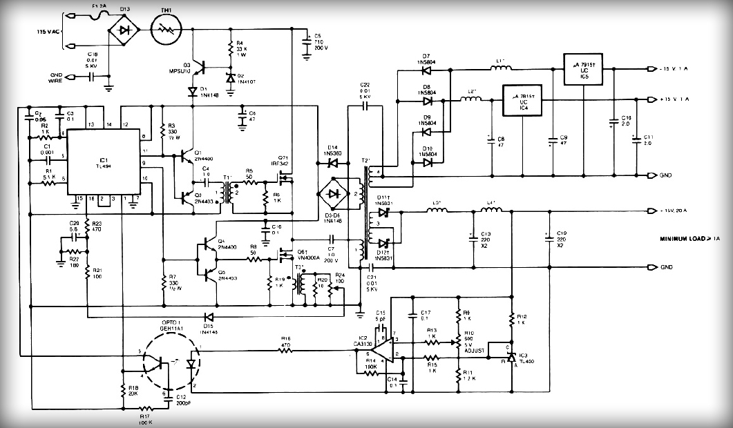
Multiple Output SMPS circuit - Electronic Circuit

transistors - MOSFET Power Supply Explained - Electrical Engineering
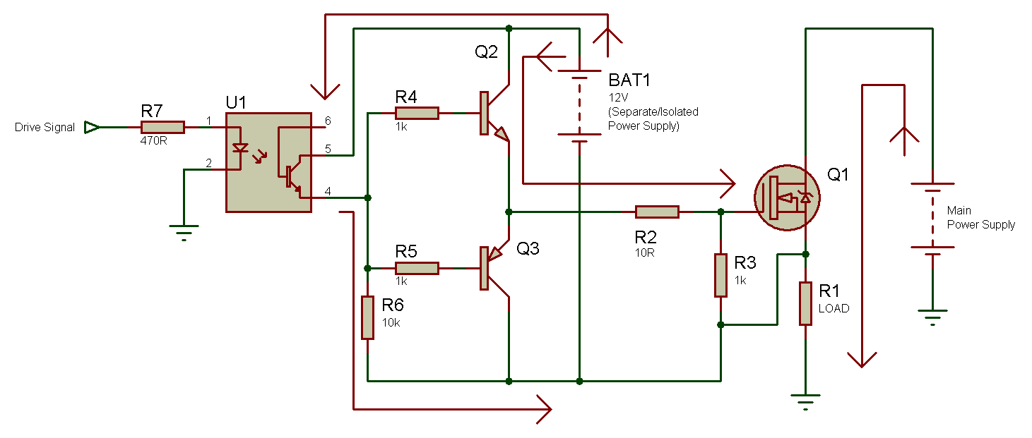
MOSFET as a power supply output switch - Page 2

Smps Circuit Diagram Using Mosfet - nerv
